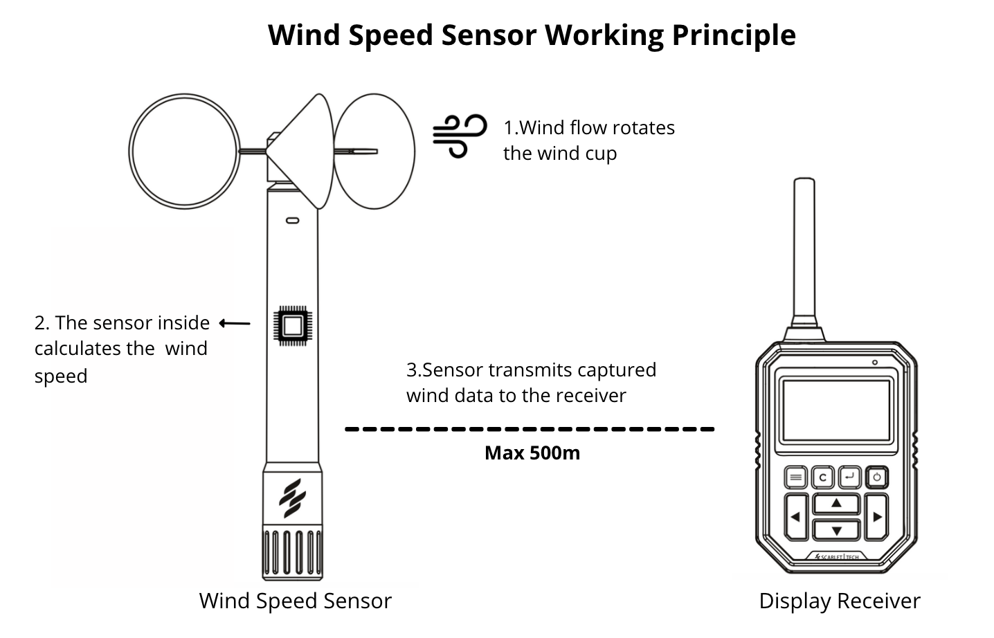
Aluminum alloy housing three cup wind speed sensor Circuit Diagram Today in this tutorial we will make a Wind Speed Meter Using Anemometer & Arduino and display the wind speed on 0.96 inch OLED Display in m/s. The NPN pulse output Anemometer sensor is a 3 cup type Anemometer that is capable of measuring wind speed up to 70-meter per seconds or 156 mph. It is composed of a shell, the wind cup, and the

The sensor can measure wind speed ranging from 0 to 40 m/s and wind direction from 0 to 360 After assembling the sensor as per the circuit diagram above, lets move to the coding part of this project. According to the above table the inquiry frame for getting the Sensor reading hexadecimal is as follows: 1.
Measure Wind Speed with Ultrasonic Anemometer & Arduino Circuit Diagram
Connect the sensor to the Pico, and write a simple code to get wind speed values in different units. A voltage divider is a simple circuit that reduces a large voltage into a smaller one. Using 2 resistors and an input voltage, we can create an output voltage that is a fraction of the input. which will correspond to the maximum wind
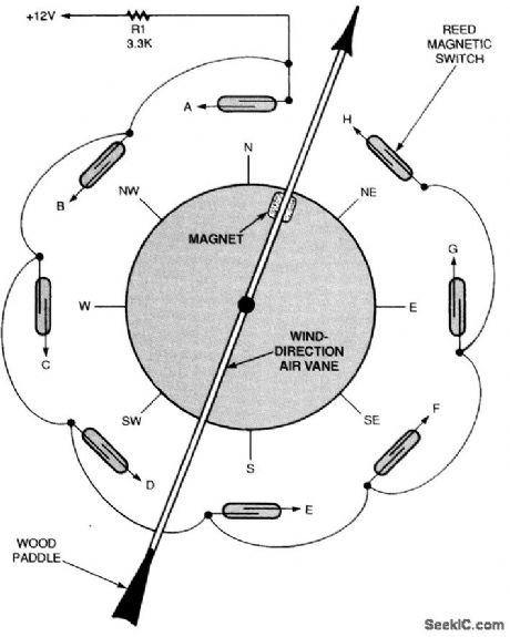
Use the 3 different colored wires to connect the sensor module. Insert the Hall module and point the sensor facing the magnet at a distance of 2 to 4 mm. Test if the rotation of the shaft does not hit the magnet with the sensor. Use a 3.7 V battery to test if the module responds to the approach of the magnet by turning the led to each contact.
Raspberry Pi Pico with Anemometer: Measure Wind Speed (Arduino IDE) Circuit Diagram
Measuring Wind Speed & Testing the Device. Once you upload the code to the Arduino Board, the LCD Display will start displaying the wind speed. When the anemometer cup is stable the LCD will show a speed of around 0m/s. The speed will vary or increase when the sensor is taken in a windy region.